Blog 1
- Yujie Lin
- Nov 19, 2023
- 4 min read

Hi, Welcome to the first blog of my CPDD journey. In this blog, I will be sharing with you about gears and my experience during my practical session. Hope you enjoy
To start things off, I will first go through the definition of gears and its relationships.
Definition and relationships of gears
gear module (m):
Refers to the size of the gear teeth. The unit for module is mm. The larger a module
number, the larger is the size of the teeth. Gears that mesh together are having the same module

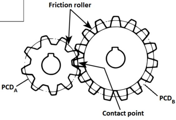
pitch circular diameter (PCD):
The Pitch Circular Diameter is an imaginary circle through the contact point of meshing gears, representing the diameters of two friction rollers in contact, both moving at the same linear velocity.
relationship between gear module, pitch circular diameter and number of teeth.
Relationship between Gear Module (m), Number of Teeth (z) and Pitch Circular Diameter (PCD):
The larger the module, the larger the gear teeth, the fewer number of teeth, and thus, the larger the Pitch Circular Diameter. Conversely, a smaller module corresponds to smaller gear teeth , fewer number of teeth and a smaller Pitch Circular Diameter. This is linked by the equation m=PCD/z
Relationship between Gear Ratio (speed ratio), Output Speed and Torque for a pair of gears
Gear Ratio:
The ratio of the number of teeth on the output gear to the number of teeth on the input gear.
GR= z(output)/z(input)
Speed Ratio:
Speed ratio is the reciprocal of the gear ratio.
SR= 1/GR
Torque:
The measurement for rotational force
Relationship:
When Gear ratio is less than 1 it is a speed multiplier. When gear ratio is more than 1 it is a torque multiplier
High Gear Ratio, Low output speed, High Torque.
Low Gear Ratio, High output speed, Low Torque
That is all you need to know about gears, right now I will sharing with you on how to better design a hand-squeeze fan using gears.
How can I design a better hand-squeezed fan
Below is a video of a hand-squeezed fan that my group made during practical and the gear layout

Improvement idea:
Since we want an efficient design that maximizes the airflow generated with each hand-powered squeeze or rotation. I suggest that we replace the driven gear with one with lesser teeth so that we can decrease the gear ratio and make it lesser than 0.1 so that it can be a better speed multiplier. Thus producing more wind.
Now I will be sharing my teams bottle challenge experience.
How my team arranged the gears provided in the practical to raise the water bottle?
My team was able get the max gear ratio of 26.67, unfortunately we were unable to finish building it as we had to disassemble our first design which had a gear ratio of 17.78. So the information below will be based on the gear setup that resulted in a gear ratio of 17.78. Thankyou for your understanding.
Calculation of the gear ratio (speed ratio):

Speed ratio= 1/17.78= 0.056
The photo of the actual gear layout:

Calculation of the number of revolutions required to rotate the crank handle:
For this part, I will be using the gear ratio 26.67

Apologies that I do not have a video of the turning of the gears to lift the water as my group wasn't able to finish constructing our design
Reflective Journal
Before this practical, i thought gears were just rotating rings for turning things. However after this practical, I learnt the fundamentals of gears. Starting from the relationship between Gear Ratio, speed ratio, Output Speed and Torque. To how to arrange a gear setup in a way that it acts as a speed multiplier or torque multiplier.
I also learnt the importance of gears and how it functions. For example, gears can multiply torque, providing mechanical advantage. This is essential in applications where increased force or torque is needed, such as in automotive transmissions and heavy machinery. Another example is gears allow for speed reduction or increase by altering the ratio of the number of teeth between the driving and driven gears. This is valuable in optimizing the speed of different components within a system to match specific requirements.
During this practical, I was challenged with the task to design a water lifter using gears. At first I thought it was simple as the 4 videos provided to us was easy to understand. However, I realised that it was not as easy as i thought it would be. Because there were many gears given, meaning that there are lots of different designs. This resulted in my group not being able to finish assembling our design. However, I am still proud that we still managed to derive to the correct gear ratio. As for the hand-squeeze fan, it took me and Dhasna quite awhile to assemble it because there were some mistakes made. For instance, a small gear out of place caused the fan being unable to work, highlighting the significant impact that even minor components can have on a gear system. This emphasizes the crucial role of attention to detail in both operation and design processes.
All in all, I really enjoyed this practical, as it challenged my mind to think hard at the same time exposing me to more engineering concepts. I also wish i can make good use of this practical to make my prototype at the end of this CPDD module.
That is all i have for this documentation on gears, i hope you guys like it. See you in the next blog where i will be sharing about Arduino programming. Thankyou


Comments